https://learn.sparkfun.com/tutorials/fingerprint-scanner-gt-521fxx-hookup-guide
Hardware Overview
Features
The GT-521F32 and GT-521F52 have a lot in common with the previous
models. They have the same protocol commands and packet structure. Code
that was implemented for previous models should be functionally the
same. The fingerprint scanner has the ability to:
- Enroll a Fingerprint
- Identify a Fingerprint
- Capable of 360° Recognition
However, there are a few differences in the boards. These include:
- Different Board Layout
- 4x Mounting Holes
- 2x JST SH Connectors
- Touch Interface
One significant difference to keep in mind when integrating the
fingerprint scanner in a project is the number of fingerprints that the
device can hold. The GT-521F32 costs less but it can hold only 200
fingerprints. The GT-521F52 is slightly more expensive but it can hold
3000 fingerprints.
| Technical Specs |
GT-521F32 / GT-521F52 |
| CPU |
ARM Cortex M3 Cortex |
| Sensor |
optical |
| Window |
16.9mm x 12.9mm |
| Effective Area of the Sensor |
14mm x 12.5mm |
| Image Size |
258x202 Pixels |
| Resolution |
450 dpi |
| Max # of Fingerprints |
200 / 3000 |
| Matching Mode |
1:1, 1:N |
| Size of Template |
496 Bytes(template) + 2 Bytes (checksum) |
| Serial Communication |
UART (Default: 9600 baud) and USB v2.0 (Full Speed) |
| False Acceptance Rate (FAR) |
< 0.001% |
| False Rejection Rate (FRR) |
< 0.01% |
| Enrollment Time |
< 3 sec (3 fingerprints) |
| Identification Time |
<1.5 |
| Operating Voltage |
3.3V ~ 6Vdc |
| Operating Current |
< 130mA |
| Touch Operating Voltage |
3.3Vdc |
| Touch Operating Current |
< 3mA |
| Touch Standby Current |
< μ5 |
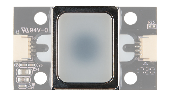
The image below shows the fingerprint scanner’s optical sensing area where the device will be able to scan your fingerprint.
There is a marking next to the JST-SH connector that indicates
polarity. The JST-SH connector breaks out the pins for serial UART and
power. While the input voltage is between
3.3V and 6V, the UART’s logic level is only
3.3V. You will need a
logic level converter or
voltage divider to safely communicate with a 5V device.
Note: Make sure that you are connecting to the correct JST
connector indicated by the polarity marker and capacitors. The JST
connector on the other side of the board are not connected to the same
pins for serial UART.
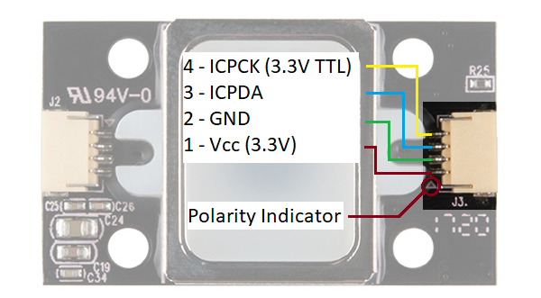
The GT-521F32 and GT-521F52 have the ability to sense if a finger is
placed on the optical sensing area. Upon contact with the metal frame
around the optical sensing area, the ICPCK will output 3.3V (HIGH).
Otherwise, the ICPCK will be 0V (LOW)
| Touch State |
ICPCK Pin Status |
| Finger Initially Touching the Frame |
LOW => HIGH |
| No Finger Touching |
LOW => LOW |
| Finger Touching the Frame |
HIGH => HIGH |
| Removing a Finger From the Frame |
HIGH => LOW |
Note: If the fingerprint scanner is powered from the UART side, you will need to still provide 3.3V to power the touch interface. The GND is connected to GND plane.
Hardware Hookup
The fingerprint scanner requires a serial UART connection and
power. There are a few options to connect to the sensor depending on
what UART device you are using. The easiest would be to use an FTDI but
you can also use any microcontroller that has a UART.
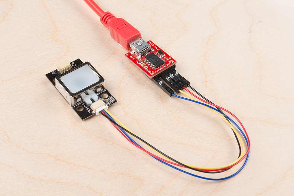
1.) Connecting w/ a 3.3V FTDI
Option 1: Qwiic Cable
To connect the fingerprint scanner to your computer, it is
recommended to connect the JST SH cable to a USB-to-serial converter.
Here are the minimum required parts you would need to get started:
Below are the following connections you would need to make with the JST-SH connector labeled as J2:
| Fingerprint Scanner [Pin #] |
FTDI 3.3V |
| UART_TX (3.3V TTL) [Pin 1] |
RX |
| UART_RX (3.3V TTL) [Pin 2] |
TX |
| GND [Pin 3] |
GND |
| Vin (3.3V~6V) [Pin 4] |
3.3V |
After connecting, the setup should look like the image below.
Note: The colors of the Qwiic Cable are standard for
I2C
connections, not UART, so the colors will not match typical standards
for colored cables. For example, the red wire in this circuit connects
Rx to Tx. Double check your connections before powering the scanner.
Option 2: Making a Custom Adapter
If you are using the
JST SH Jumper 4 Wire Assembly
instead of the Qwiic cable, it is highly recommended that you make a
custom adapter by soldering to the ends of the wire for a secure
connection. This will ensure that the connection is not loose when
inserting it into female header sockets of an FTDI or the
RedBoard/Arduino Uno. The cable wire is small compared to the female
header socket. A small bump can mess with the serial UART or power
between the fingerprint scanner and converter. This may require you to
reconnect the scanner to your computer or device. Making an adapter will
also provide quick access to the small 4-pin JST-SH connector that is
on the scanner.
For more information on how to make a custom adapter, please refer to
the older tutorial. Remember, the pin locations are the same so the
adapter can work with the current fingerprint scanner.
 There is a marking next to the JST-SH connector that indicates
polarity. The JST-SH connector breaks out the pins for serial UART and
power. While the input voltage is between 3.3V and 6V, the UART’s logic level is only 3.3V. You will need a logic level converter or voltage divider to safely communicate with a 5V device.
There is a marking next to the JST-SH connector that indicates
polarity. The JST-SH connector breaks out the pins for serial UART and
power. While the input voltage is between 3.3V and 6V, the UART’s logic level is only 3.3V. You will need a logic level converter or voltage divider to safely communicate with a 5V device.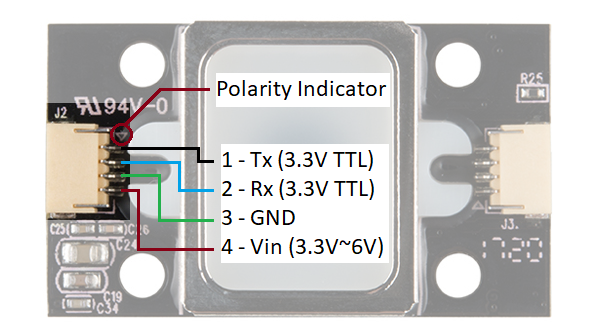
 The GT-521F32 and GT-521F52 have the ability to sense if a finger is
placed on the optical sensing area. Upon contact with the metal frame
around the optical sensing area, the ICPCK will output 3.3V (HIGH).
Otherwise, the ICPCK will be 0V (LOW)
The GT-521F32 and GT-521F52 have the ability to sense if a finger is
placed on the optical sensing area. Upon contact with the metal frame
around the optical sensing area, the ICPCK will output 3.3V (HIGH).
Otherwise, the ICPCK will be 0V (LOW)

Comentarios
Publicar un comentario